Abstract—Automation can easily increase the efficiency of the Industries the main aim of our concept is to monitor and control the Industrial substation by using SCADA. The power grid was previously monitored by Manual and now it can be monitor by using Internet.
Main functions of substation automation include accurate fault location to prevent false tripping and to minimize the area affected by the fault. We can access data securely from any part of the world by point to point communication using internet. Substation automation increase reliability and performance of electrical protection, advanced disturbance and event recording capabilities is possible.
The changes in load and stability affects the operation of a power system. The increase in power conception lead to the construction of many substations. This lead to the automation of substation for reducing the complexity of power transmission.
Keywords—RTU, Protocol, Electrical distribution, Substation automation, SCADA, KSEB.
Nowadays the electricity problems are affecting the productivity and efficiency of the industry. This can be eliminated by automating the industrial substation. Through substation automation reliability and performance of electrical protection is increased, advanced disturbance and event recording capabilities are gained.
This system can monitor and control the circuit-breakers operated on the site, to achieve data acquisition, measurement, parameter adjustment, and various signal alarms.
This monitoring system uses monitoring hosts to call and monitor the load status, load distribution curve, accident statistics, important alarm, working status, and other electricity monitoring data of various substations. In RTU automated substation, the power equipment, their communication and computers are interdependent. The datas from substation equipment is communicated with the SCADA systems by using RTU.
This monitoring system uses monitoring hosts to call and monitor the load status, load distribution curve, accident statistics, important alarm, working status, and other electricity monitoring data of various substations. In RTU automated substation, the power equipment, their communication and computers are interdependent. The datas from substation equipment is communicated with the SCADA systems by using RTU.
The main advantage of using SCADA system is that monitoring and controlling can be done easily and reduce the human labour [1]. The monitoring system and real time supervision system of the field devices and the real-time status are currents, voltages, pressures, temperatures, contacts, etc. This supervision is made through digital equipment and special sensors that are installed in the field devices of the substation. The data are collected and processed in a data acquisition and control unit (UAC), to thereafter through a communication network, using desirably a protocol standardized international sent to a central computer located at the control building of the substation and later to the operation centers and so allowing a remote supervision. Measured values reflect different time varying quantities, such as voltage, current, temperature and tap changer positions, which are collected from the power system. They fall into two basic type and digital. All analogue signals are transformed via an A/D converter to binary format because treated as momentary-value that they have to be normalized before storing [2].
The substation automation system in a given substation had to exchange enormous information to deliver the desired performance. This required considerable customization through protocol converters that were proprietary (Manufacturer Specific) in nature, but that was not compatible with a multi-vendor environment. The SCADA applications and individual device vendors share common tag data bases. Specialized point to point link to IEDs applications must deal with numerous Protocols, Data formats & Data addressing. There is virtually no link to other applications. Communication path must be reconfigured, when new device and applications are added. The most recently widely used technology like OPC was mainly adopting this approach [3].
It is very difficult to know the actual losses on the distribution network. Generally, rules of thumb are used to estimate the power losses [4].
The basic information about the challenge for the EPS is to provide a quick response to the undesirable effects, maintaining reliability and competitive prices [5].
II. NEED FOR SUBSTATION AUTOMATION
The basic needs for the industrial substation automation are:
Substation automation is required in Industries to increase reliability and performance of electrical protection of circuits in substation, which will affect the efficiency of power distribution.
Advanced disturbance of the power and event recording capabilities can be achieved by using RTU, which will record the amount of unit used by the industry in each sec.
Display of real time substation information is possible by using multi-function meter and SCADA, which is required for getting open access from KSEB.
Remote switching and advance supervisory control can be done easily by the output module of RTU which is connected to the coil relay for more efficiency.
The high-power EMF produced in the transformers during step up or step down of the power that is distributed through grid lines, can affect human brain cells.
Advanced automation functions like intelligent load-shedding can be done for easier, faster and safer during the power transmission time or at any short-circuit problems.
The main circuit breaker can be controlled by using internet instead of manual control which is possible by the use of RTU and the communication unit with SCADA.
The hacking of the Industrial substation or malfunctioning of it can be identified and alarm can be set for the security purpose of the power transmission.
Financial Need for Substation Automation
The factors that lead the industries in Kerala to automate their substation is explained below.
Kerala State Electricity Board Ltd (KSEB Ltd) is a public-sector agency under the Government of Kerala, India, that generates, transmits and distributes the electricity supply in the state.
Kerala State's average daily consumption is 74.77 million units per day which cannot be generated from the hydro power station alone.

Figure 1. Industrial Power Distribution Diagram
To satisfy this energy need KSEB has executed purchase of power from north region of India.
But, KSEB have to bear the transmission losses in grid line during the power distribution.
KSEB then sell this power to industries for higher unit cost which increased the profit of KSEB.
Many Industries closed in Kerala because of the high electricity bill that they need to pay.
For supporting the industries that need more units of power, the Kerala government given permission for open access.
By taking open access, the industry can directly purchase low cost power from northern power generators.
For taking open access the industry should automate their substation by using RTU and SCADA.
After implementation of this project the cost of each unit will be reduced as per the present price.
But the industry should pay maintenance charges to KSEB for transmitting power from the north through grid lines.
III. CONCEPT MODEL
The conceptual model that we suggest for the substation automation system is given below.
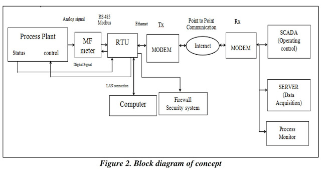

Our system is developed for controlling the main CB of the industrial substation and to collect, display and store the electrical parameters from the substation for the future reference. The present status of the substation is also transferred to the receiver through VPN connection, where the datas are safely uploaded for the KSEB control. The hacking is eliminated by using the NTP server which will update the time of the system in each sec.
The main components used for substation automation system are the MF meter, RTU, Modem, and SCADA control. The MF meter collects the electrical parameters from the industrial substation and display it and also transmit the datas to the RTU. As per the data received from the process plant the RTU will control the main circuit breaker. The RTU can be configurated by using the PC through Ethernet cable. The IP address for the SCADA controller is configurated in the RTU. Through point to point communication the substation is controlled by using the SCADA system.
IV. ASSEMBLED MODEL
The assembled substation automation model developed by us is shown below along with the various components that are marked on the figure itself.


V. WORKING
For the protection of RTU panel first Siemens MCB is connected with the power supply, then the indicator light is connected to output lines of the first MCB. SMPS switch is also connected to the output power line of first MCB to reduce 240V to 24V input power supply, then it is connected to the second MCB, then to RTU Power Module.
The current and voltage input is taken from KSEB incomer and connected to MF meter. The output from MF meter is connected to the RTU communication module. The input from ammeter and voltmeter is connected to RTU input module through solid relay. The output from key switch is connected to RTU input module. The output module of the RTU520 is connected to the Main Circuit Breaker through coil relay.
The RTU is connected to the lap through Ethernet cable, then by using RTU Utility software configuration is done. The point to point communication is developed by using BSNL ONT server and router is connected for providing Wi-Fi network.
The breaker control and substation monitoring data is transferred to KSEB SCADA controller through point to point communication. Then the KSEB officer can see the present status of the industrial substation and the data about the power usage of the industry in each second will be stored. The main circuit breaker of the industry can be controlled by using SCADA.
VI. PROFIT ANALYSIS
By automating the substation, the industries are getting many benefits. By taking open access for the electricity used by the industry the profit of the industry will increase.

The following profit analysis is done based on the approximate electricity units used by an industry.

VII. CONCLUSIONS
Substation Automation will improve routine asset management, quality of service, operational efficiency, reliability, and security.
The three parts of the system are assimilated with the advanced communication and measurement technology. As added advantage to the existing system, the proposed methodology can monitor the operating situation, easily detect and locate the fault of the feeders and status of breakers.
The information from the system helps in apprehending the advanced distribution operation, which includes improvement in power quality, loss detection and state estimation.
Also can eliminate the high cost of electricity by implementing this concept in the industrial substation. A small fault in the electrical circuit may damage the entire Industry. By our concept the problems faced by the industry can be eliminated and the complete circuit protection can be achieved.


 Ewaybot MoRo
 Aristotle by Nabi